
Industrial PCB Manufacturing: From Design to Assembly
Rugged, high-performance PCBs
- High-reliability PCBs for factory.
- meeting IPC-A-610 Class 3
- Extended temperature range and vibration-resistant designs.
- UL/ATEX certification for hazardous locations.
- Predictive maintenance and IIoT-ready assemblies.
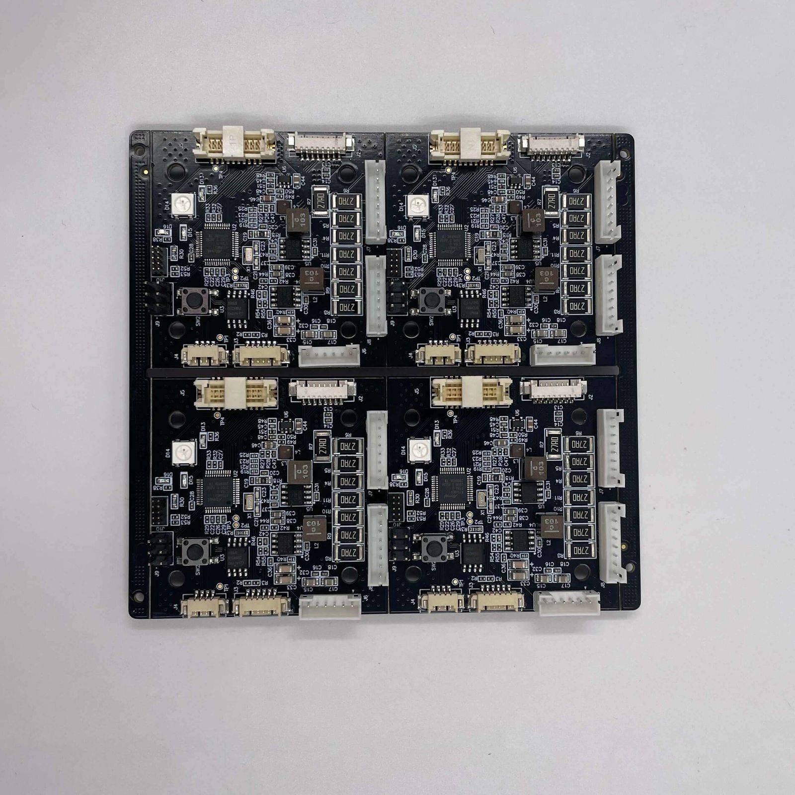
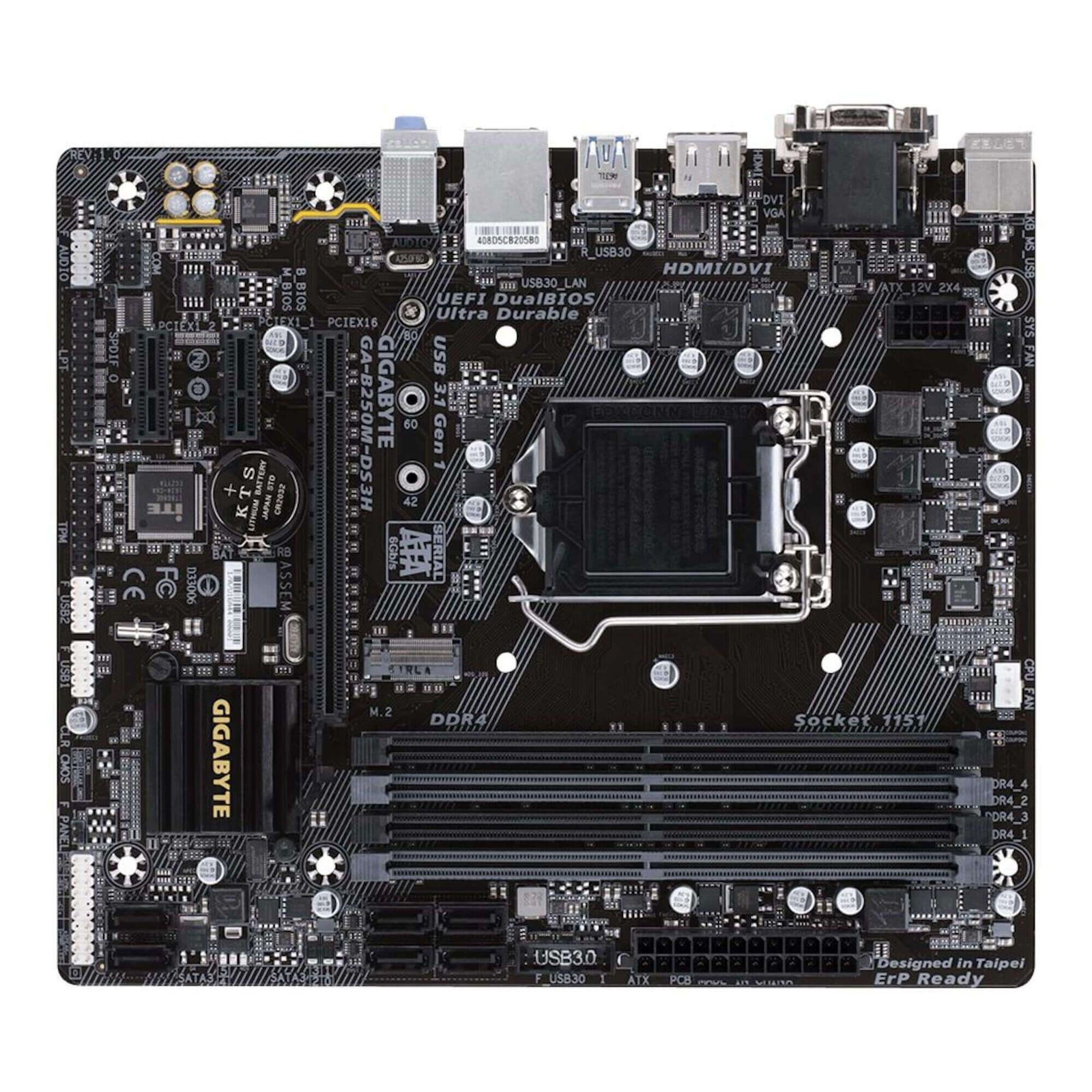
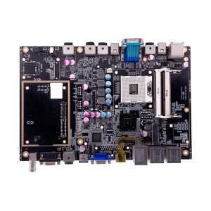
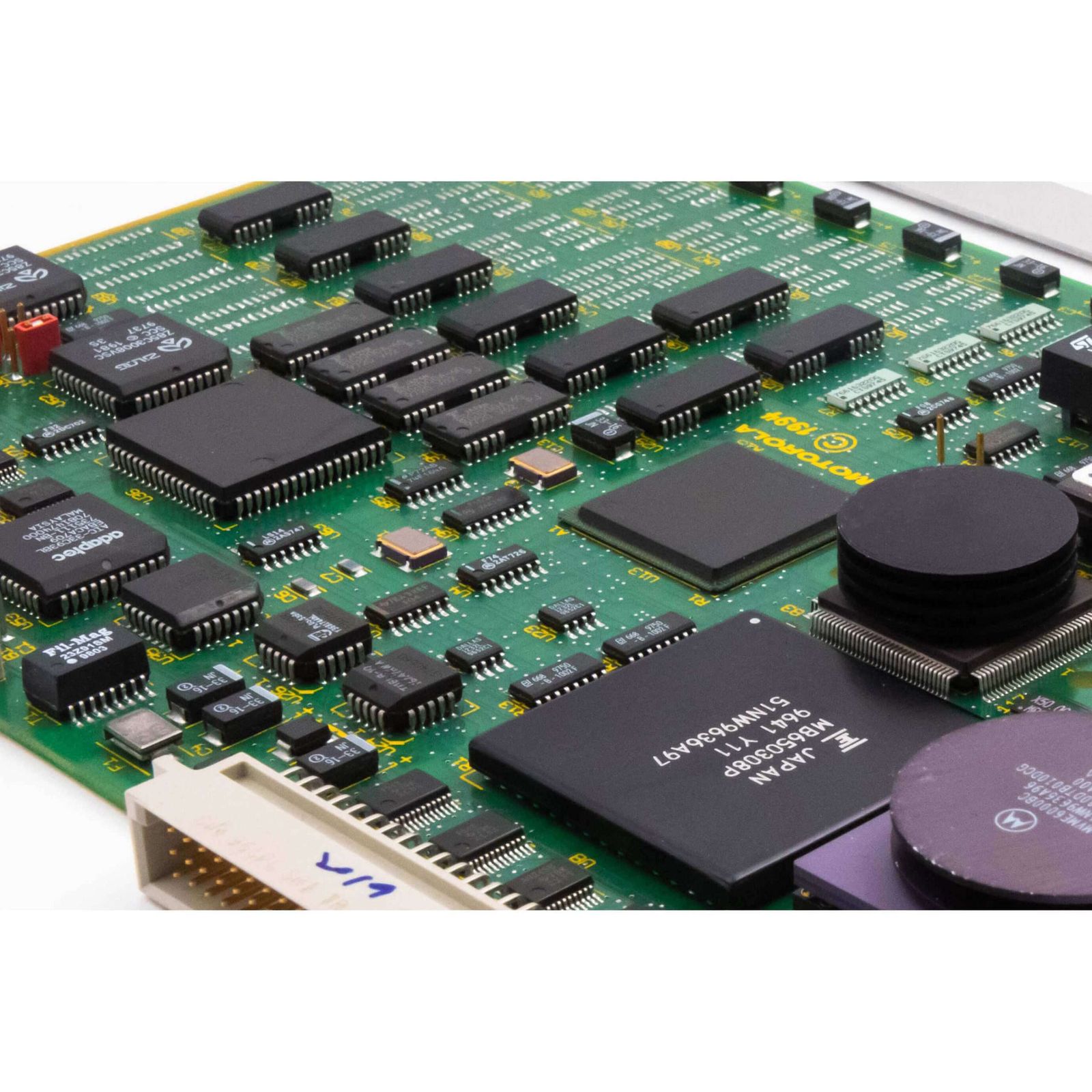
Industrial Circuit Board Sample Display
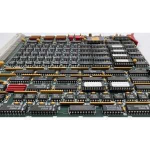
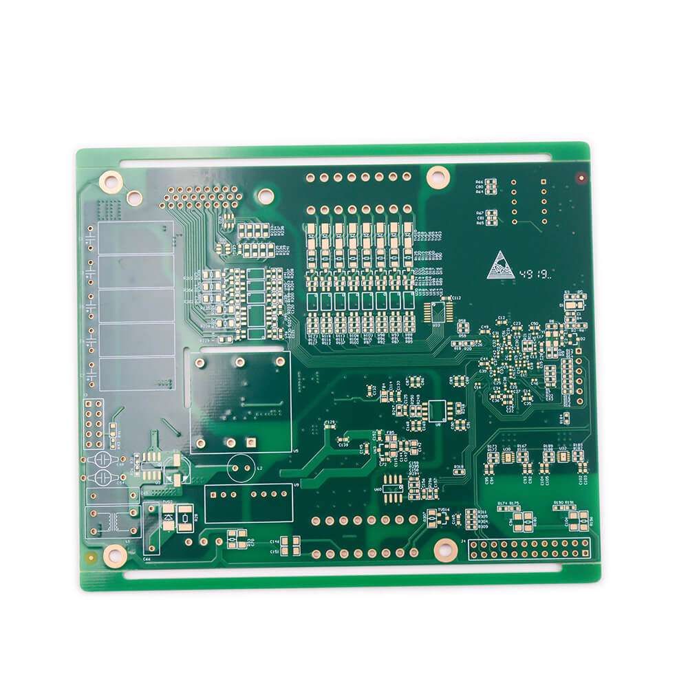
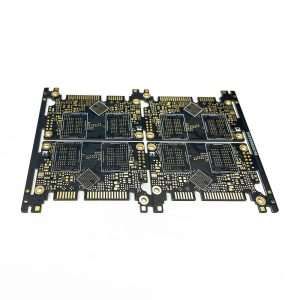
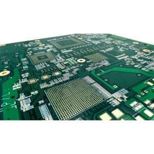
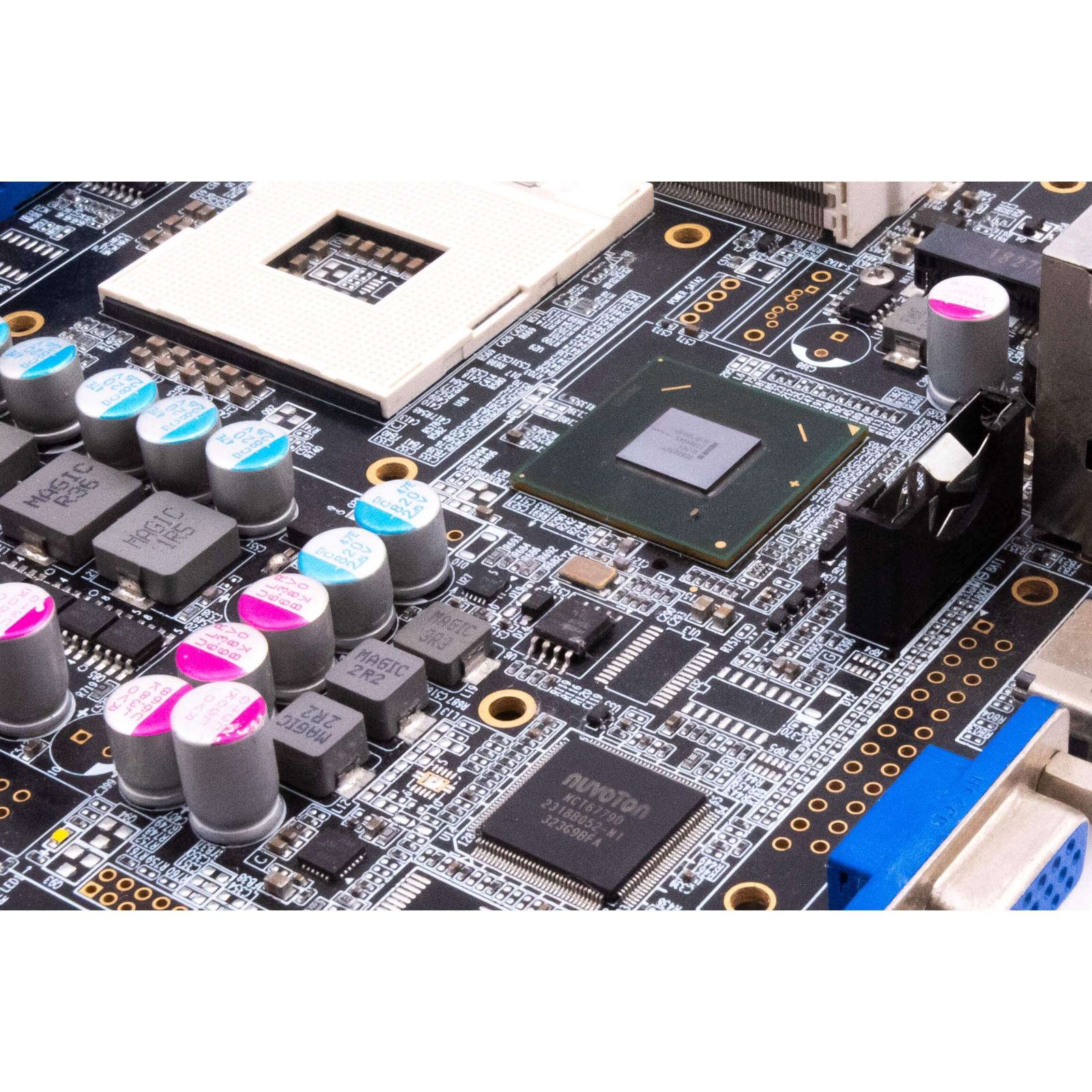
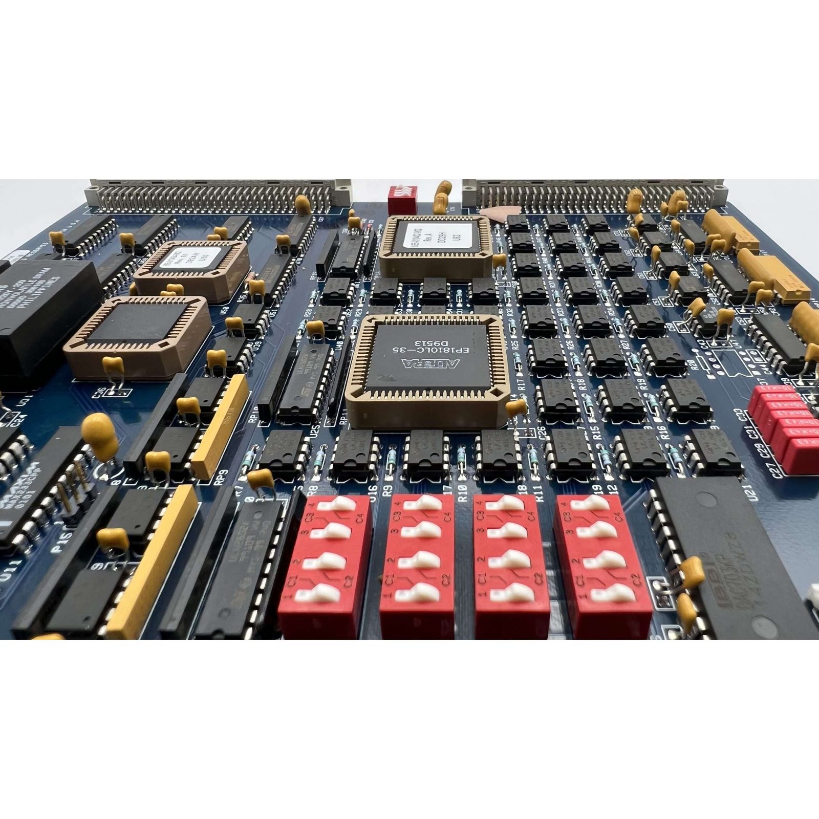
Industrial PCB Fabrication
Industrial PCB Manufacturing Capabilities
| Maximum number of layers | 36 |
|---|---|
| Board thickness | 0.25″ |
| Maximum Panel Size | 23.62″x39.37″ |
| Impedance toleranc | -/+ 5% |
| Minimal Laser Drilling | 0.002″ |
| Minimal Mechanical Drilling | 0.0059″ |
| Min trace and space | 0.0015″ |
| Drilling process | Blind Buried Vias |
Industrial Control PCBA Supplier Industry Standard
- Industrial SIL: Stands for Safety Integrity Level, and measures the safety performance of Safety Instrumented Systems (SIS).
- IEC 61511: Is a process industry-specific standard that provides guidance for the specification, design, installation, operation, and maintenance of safety instrumented systems (SIS) in the process industry.
- IPC-6012: Specifies the qualification and performance requirements for rigid printed circuit boards, including base material, conductor configuration, hole requirements, surface and internal conductors, and marking.
- IPC-2221: Defines the design requirements for printed circuit boards, including board layout, trace width and spacing, via dimensions, and other design aspects.
- UL 94: Tests the flammability of plastic materials used in the construction of electronic equipment. PCBs that meet this standard are made of flame-retardant materials.
- RoHS: Is a directive that restricts the use of six hazardous substances in the manufacture of electronic and electrical equipment, and industrial PCBs must comply with this directive.
A Comprehensive Guide to Industrial Control PCBs
Industrial Control PCB Board Definition
Industrial control boards are specific circuit boards used for industrial control operations. They are different from commercial off-the-shelf boards as they are created according to specific requirements. These boards have general-purpose inputs and outputs (IO) that can be used to connect peripheral devices such as valves, motors, and sensors.
There are also dedicated industrial control PCB designed for specific operations, such as temperature control boards. These boards have inputs connected to a thermocouple and outputs connected to heating contractors, which control the heat of devices and environments.
Industrial control boards are made of two materials: a non-conductive base and copper traces and pads. The copper traces and pads serve as interconnections between components assembled on the PCB board. These boards can be single layer, double layer, or multilayer PCB, depending on the complexity of the operations. For single-layer boards, there are copper traces on only one side, while for two-layer boards, traces are on both sides.
These boards are also known as universal PCB as they have programming features that allow users to set the functions according to their requirements. A programming logic controller (PLC) is an example of a general industrial control board. It operates by writing different programs and compiling inputs to perform various operations. It has digital input, analog input ports, and high-speed counter ports that provide communication operations.
Industrial PCB Design Factors
Component Layout
The placement of components on the board layout is a critical factor to consider when designing industrial control PCB boards. Improper component placement can affect the reliability and performance of the final product. During PCB board design, special care must be taken to ensure that components are installed on the board with a minimum of 100 mils space between the edges of the board and the mounted components. This ensures that the dimensions of the board and mounted holes are consistent.
EMI & RFI
In industrial applications, it is crucial to minimize the effects of Electromagnetic Interference (EMI) and Radio Frequency Interference (RFI), which can cause noise and disrupt the operation of the PCBA. To this end, FS Technology offers several strategies:
Board layout: To reduce the risk of noise coupling, separate high-frequency circuits from low-frequency circuits and keep signal traces away from power and ground planes. Signal traces should be as short as possible, while power and ground planes should be as large as possible and routed with low inductance hole connections to minimize the impedance of the power network.
Filtering components: Add filtering components such as capacitors and inductors to power and signal lines to filter out unwanted noise.
Grounding and Shielding Techniques: Enclose sensitive components in Faraday cages to block EMI and RFI.
Component Selection: Choose circuit board components with high-quality grounding and shielding. Use shielded cables to connect the board to external devices to prevent unwanted signal coupling.
Industrial Control PCB Material
The selection of materials for PCB manufacturing is critical and should be based on the specific working environment. Materials for PCBs used in industry must be able to withstand harsh conditions, such as high temperature, high voltage, humidity, vibration, and chemical exposure. Some commonly used materials for industrial PCBs are:
- Polyimide: This high-performance material can withstand extreme temperatures up to 400°C and is often used in aerospace, military, and high-temperature industrial control applications.
- Ceramic: A ceramic PCB is made of a ceramic substrate and metal traces. They have excellent thermal conductivity and can handle high temperatures and harsh chemicals. They are commonly used in power electronics and high-frequency applications.
- PTFE: PTFE or polytetrafluoroethylene is a fluoropolymer with excellent electrical insulating properties that can withstand high temperatures up to 260°C. It is commonly used in high-frequency and microwave applications, as well as harsh chemical environments.
- FR-4: This composite material made of woven fiberglass cloth and epoxy resin is the most commonly used material for general PCBs, including industrial. FR4 PCB has good electrical insulation properties and can withstand high temperatures and chemicals.
Industrial PCBA vs Commercial PCBA
| Industrial PCBA | Attributes | Commercial PCBA |
|---|---|---|
| For a specific application rather than a purpose | Design | For general use |
| Rugged to withstand harsh environments | Material | More cost-effective |
| Industrial control system | Application | Consumer Electronics |
| Stricter testing and quality control measures | Test | Relatively simple, fewer projects |
| Expensive | Cost: | Cheap |
| Class 2 or Class 3 | IPC 6011 | Class1 or Class 2 |
| Construct the PCB symmetrically around the central axis in the z direction. | Stackup Balance | Regular |
| Balance between Heavy Copper Weight and Normal Copper Weight | Copper Consistency | Regular |
| Consistent temperature distribution is necessary for uniform flow of solder during PCBA. | Thermal Consistency | Regular |